

MineMaster MS20 Shotcreter on MacLean CS3
Background
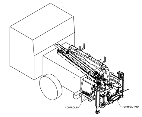
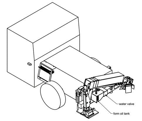
In mid 2020 MineMaster was approached by Glencore with a request for proposal to fit a MineMaster shotcreter arm onto their MacLean CS3 cassette truck. The project scope was to outfit an existing vehicle to be a single mobile shotcrete machine with a boom on the front and shotcrete mixing cassette on the rear. Two proposals were made and basic machine layouts completed, one with the MM4502 (Figure 1) and another with the MS20 (Figure 2).
The primary differences between these two proposals is the boom size. In the first option the MM4502 boom has an extra articulation point and a longer reach which was desired by the customer. However, operator visibility was found to be extremely poor with the MM4502 boom folded along the hood of the vehicle. Since safety of the operator, vehicle, and surroundings was considered paramount it was decided to move forward with the MS20 boom.
In the fall of 2020 MineMaster received the CS3 at our facility and drafted a specific proposal for fitting the MS20 boom onto the CS3 cassette truck. After setting expectations, project scope and timeline the final design and project build began.
Bumper Design
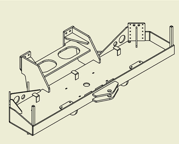
To fix the MS20 MineMaster shotcreter boom to the front of the machine we quickly realized that a replacement bumper would need to be fabricated. Clean-sheet design of the bumper was required since the old bumper was bent in multiple locations.
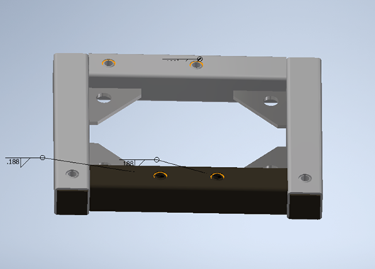
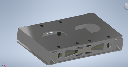
Multiple iterations were explored before the final design (Figure 5) was reached. The design requirements that went into this layout were: (1) must hold the MS20 boom, (2) must allow machine to be towed at gross weight up a 20% ramp, (3) must have provisions for mounting outrigger cylinders which will provide stability during shotcrete operation, and (5) must bolt to existing bumper bolt holes in main frame.
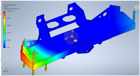
Multiple FEA analysis were preformed during the iterative design process to ensure the design was capable of holding up to the expected forces of driving, towing, hitting a wall and outrigger operation.
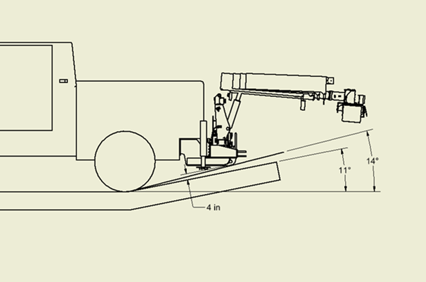
The front bumper design had to allow the vehicle to transition to a 20% grade without risk of contacting the terrain. Our model of the machine was used to evaluate ground clearance in this scenario. The chosen design allowed the vehicle to easily transition onto a 20% slope with no contact and allowed a maximum of 14 degree slope (~25 percent grade) from the front wheels to the bottom of the front bumper.
Electrohydraulic Control System
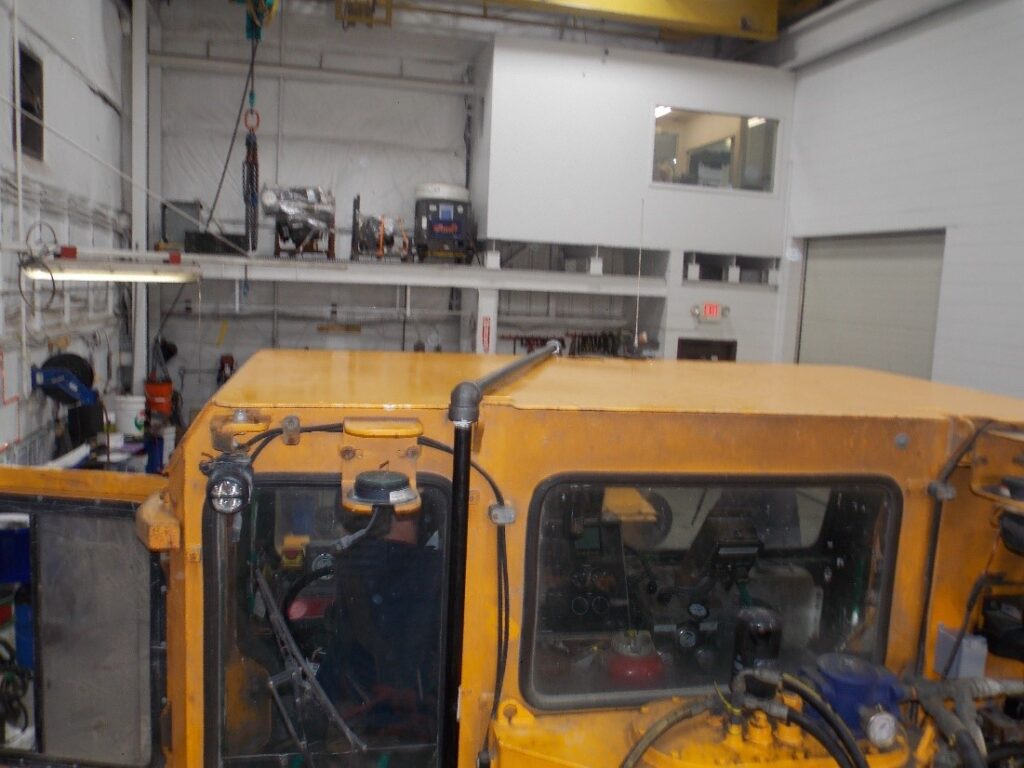
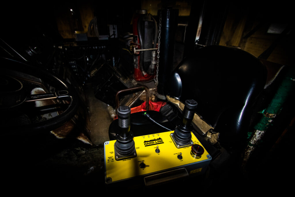
To control the boom a standard MS20 electrohydraulic control valve was used. The initial proposal was to install the valve on the front bumper, but customer requests dictated the valve bank be installed in the cab for protection. The valve was oriented in a vertical direction to fit it beside the electrical control box. Figure 8 shows the orientation of the valve bank and electrical control box. Above the electrical control box a shelf was included to hold the wireless remote and other small tools.
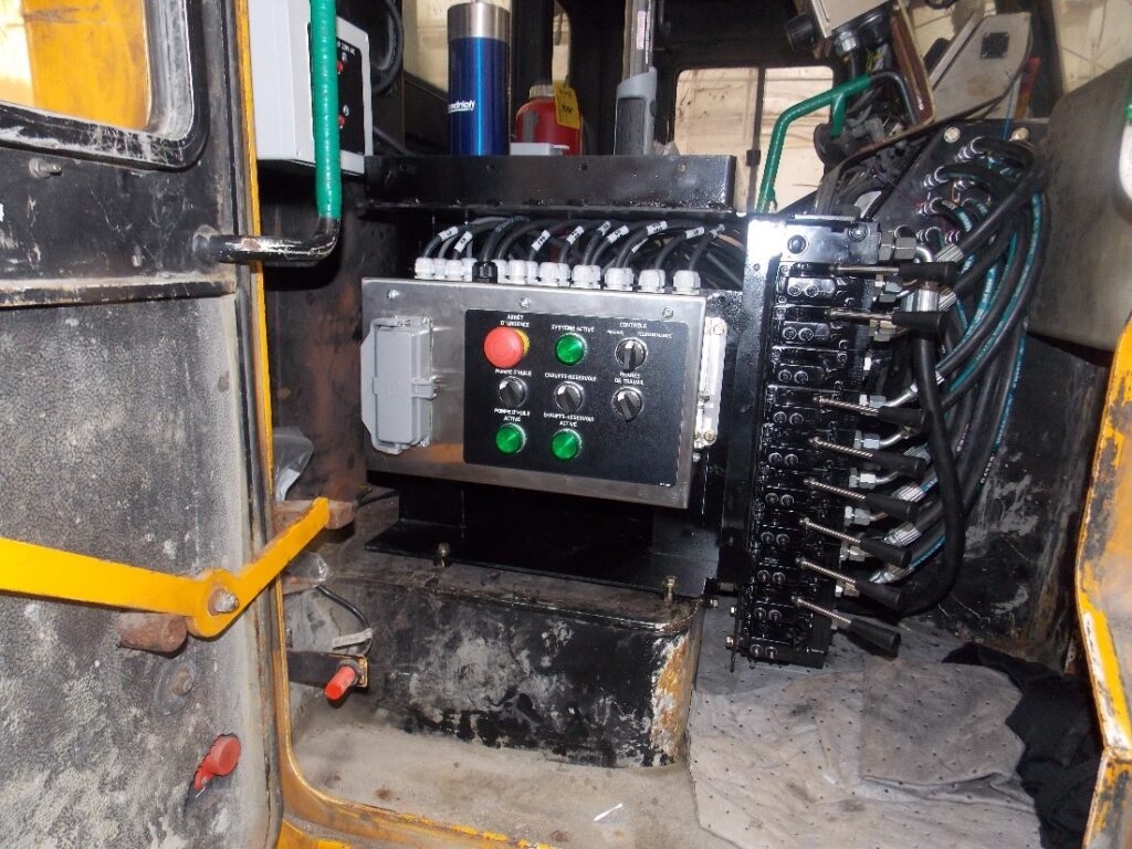
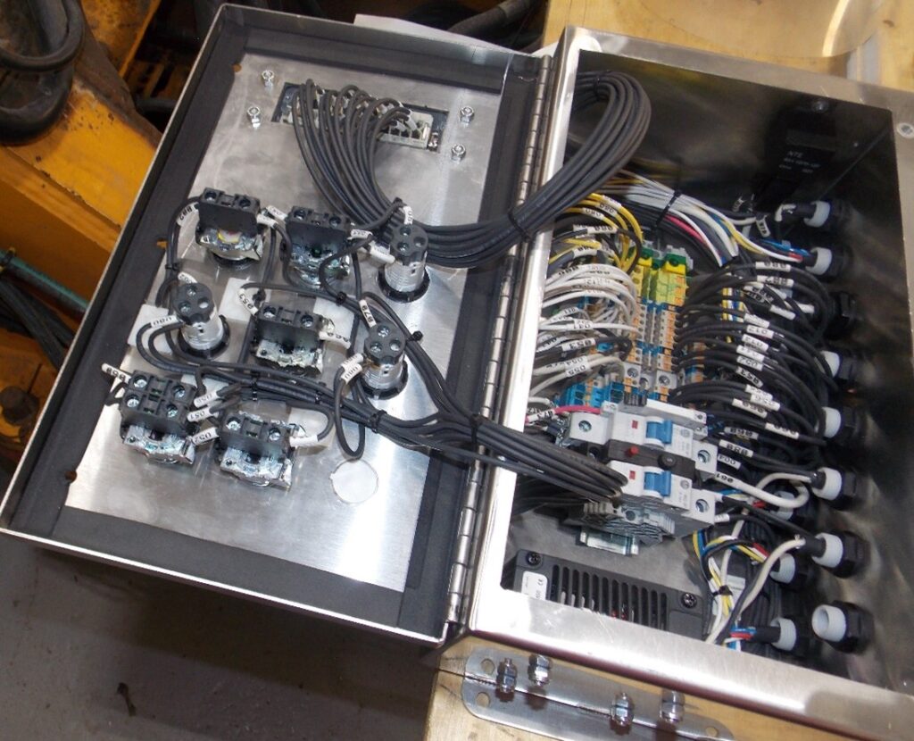
Figure 9 shows the electrical assembly of the final control box. This box contained a few modifications from our standard control box. (1) supply voltage was 24v where our standard valve requires 12v, a small DC/DC converter was installed to provide 12v power to the hydraulic valve bank. (2) An oil heater was required to ensure form oil viscosity was high enough for pumping and spraying. The heaters are controlled through an additional switch and relay installed in the control box. (3) Estop output functionality was required to ensure shotcrete pump and air compressors turn off if the operator hits the estop button. An additional relay was installed to provide one set of NO/NC contacts for controlling external equipment from the estop switch.
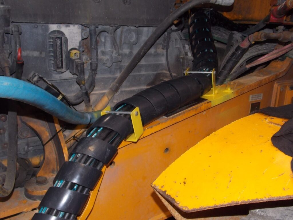
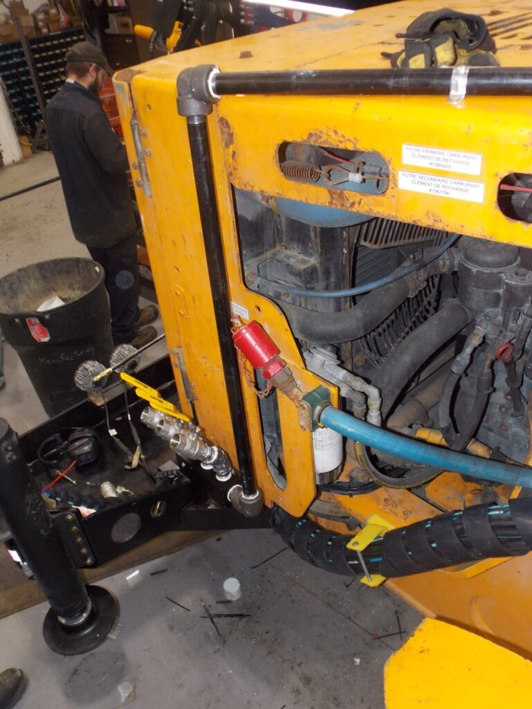
From the hydraulic valve the hoses are routed through a bulkhead in the cab, through the engine compartment on the cold side of the engine, across the bumper, and to the shotcrete boom cylinders. Multiple bulkheads were required to allow individual sections of hoses to be replaced for ease of maintenance. All hoses were secured by brackets and wrapped in heavy duty hose wrap to reduce mechanical stress.
Air Line Routing
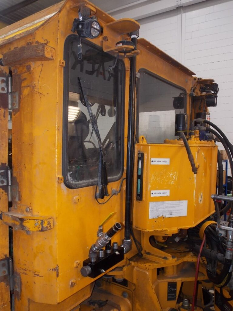
An additional customer requirement was air line running from the rear of the cab to the front with multiple bulkheads.
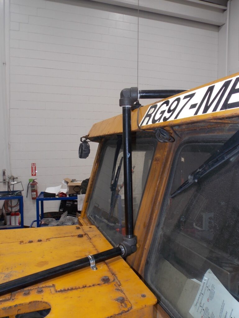
A limiting factor of this requirement was that no holes or welding were allowed on the ROPS/FOPS to secure. Therefore, rigid air line was used and secured on each side of the cab. Figures 12-15 show the air line routing over the cab.
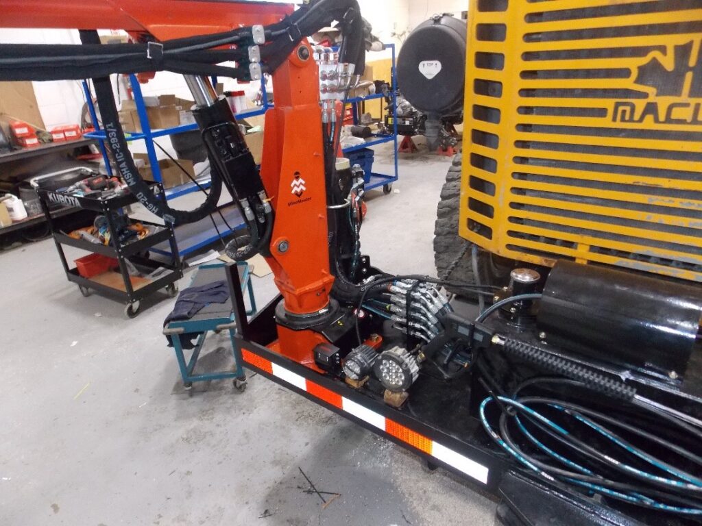
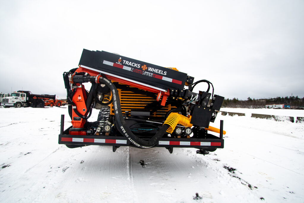
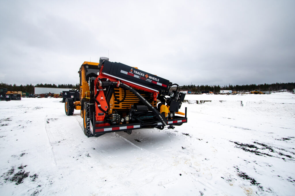
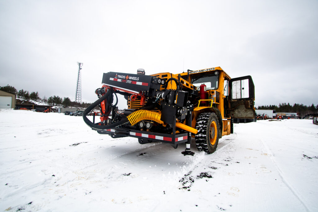
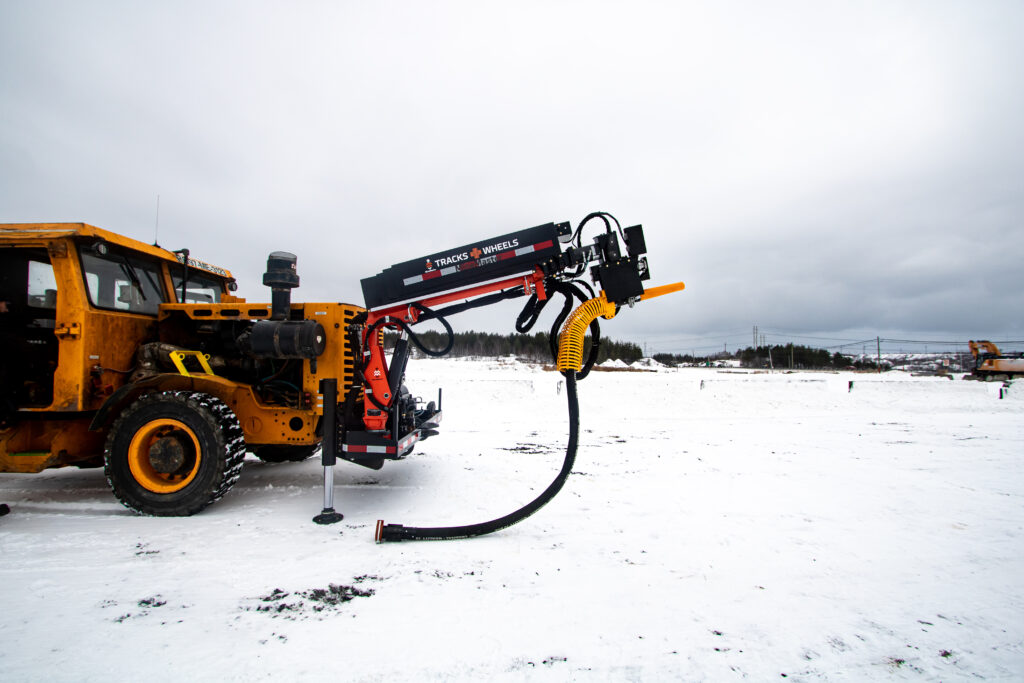
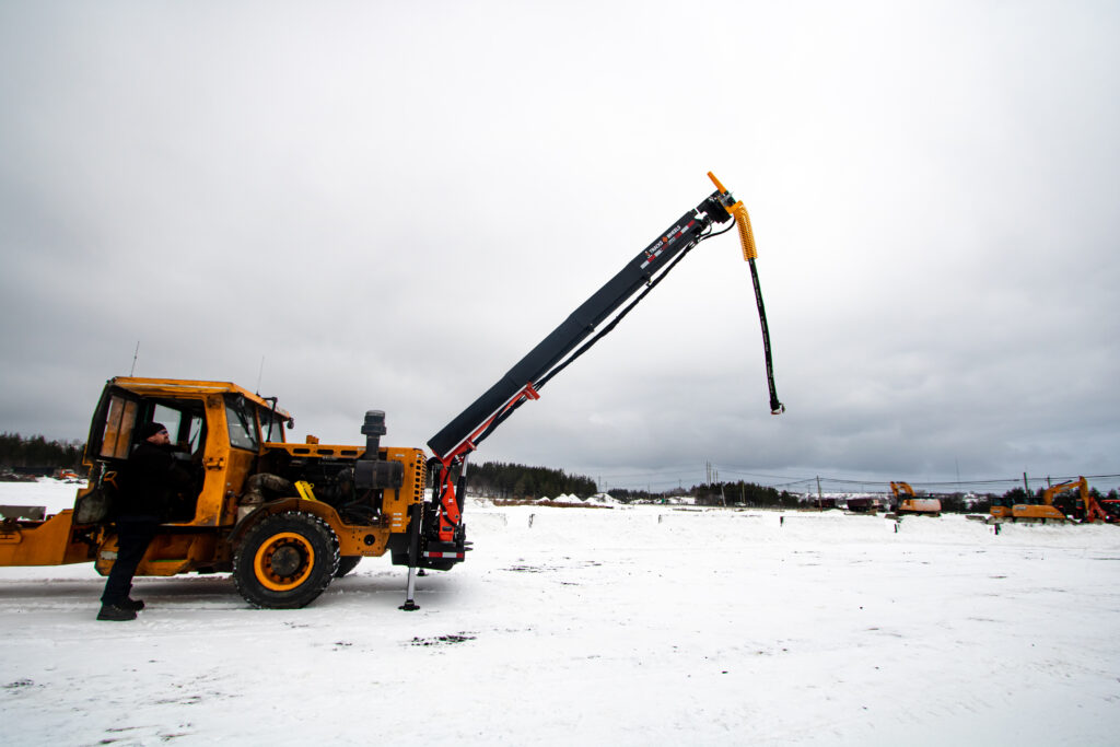
Final Product
The final product is a self-contained shotcrete unit with a wireless remote and large reach. The large CS3 base unit will enable the customer to move all required shotcrete equipment with one base machine and reduce the need for additional equipment to perform their shotcrete jobs.
Contact us if you have any questions, or would like to discuss equipment!
No responses yet